Learning SDR

Harvey Mudd College
Lesson 4 — What’s Inside the Software-Defined Radio?
(Designing one from first principles)
As we saw last time, using Euler’s identity, \(e^{i\phi} = \cos\phi + i \sin\phi\), we can write the manifestly real function \(\cos\phi\) as the sum of two complex exponentials: \begin{equation} \cos\phi = \frac{1}{2}(e^{i\phi} + e^{-i\phi}) \end{equation}
Now consider what happens if we multiply a cosine at one frequency, \(f\), by another at \(f_0\): \begin{align} \cos(2\pi f t)\;& 2\cos(2 \pi f_0 t) = \frac{1}{2} \bigg( e^{i 2\pi f t} + e^{-i 2 \pi f t} \bigg)\bigg(e^{i 2\pi f_0 t} + e^{-i 2 \pi f_0 t} \bigg) \\ &= \frac{1}{2}\bigg[ \textcolor{blue}{e^{i 2\pi (f+f_0)t}} + \textcolor{red}{e^{i 2\pi (f-f_0)t} + e^{-i 2\pi (f-f_0)t}} + \textcolor{blue}{e^{-i 2\pi (f+f_0)t}}\bigg] \\ &= \textcolor{blue}{\cos[2\pi(f+f_0)t]} + \textcolor{red}{\cos[2\pi(f-f_0)t]} \end{align} We get a cosine at the sum of the two frequencies and another at the difference frequency. If \(f\) and \(f_0\) are not too dissimilar, the difference frequency will oscillate much more slowly than \(f_0\), so that if we were to pass this product of cosines through a low-pass filter, only the difference frequency would emerge with appreciable amplitude. You can confirm that a similar separation into sine functions would take place on the lower branch of Fig. 1.
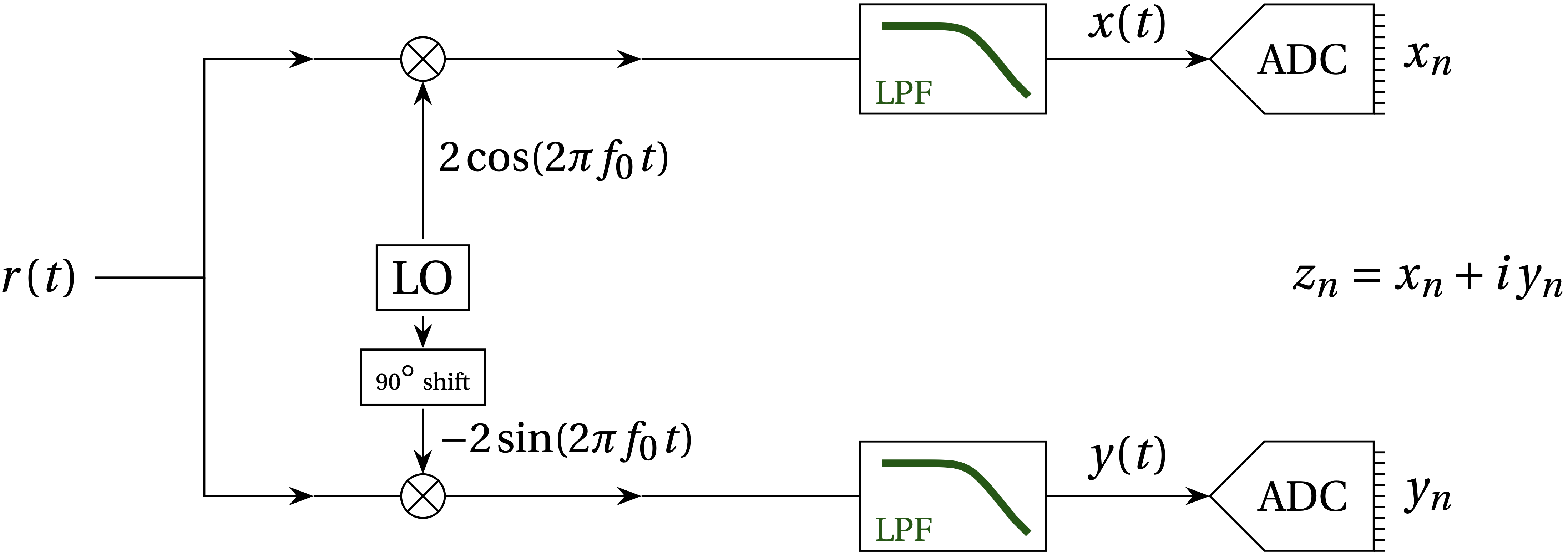
Figure 1 — Consider a real sinusoidal signal, \(r(t) = A \cos(2 \pi f t + \phi_{0})\) entering the diagram from the left. A local oscillator (LO) at frequency \(f_0\) generates \(2\cos(2\pi f_0 t)\) which multiplies \(r(t)\) on the upper branch, and a shifted version multiplies \(r(t)\) by \(-2 \sin(2 \pi f_0 t)\) on the lower branch. Each product passes through a low-pass filter and is then digitized.
As illustrated in Fig. 1, the software-defined radio has to manage two of these operations using a local oscillator at frequency \(f_0\) and a copy shifted by exactly 90° to yield the real part of the difference-frequency signal, \(x(t)\) and the imaginary part \(y(t)\) that together represent the signal at the difference frequency, \begin{equation} z(t) = x(t) + i y(t) = e^{i 2\pi (f-f_0) t} \end{equation}
Bonus: Why Zero Intermediate Frequencey (“Zero IF” or “direct conversion”)?
The receiver described here is an example of “Zero Intermediate Frequency” architecture, where the roadie-frequency signal is mixed directly down to a low frequency around 0 Hz. This is in contrast to a Super-heterodyne receiver, which first mixes the radio-frequency signal to some per-determined intermediate frequency (see examples, where optimized hardware narrow-band band-pass analog filters can then select the desired signal. This filtered signal is further mixed down to baseband (much lower audio frequencies). Why do this two-step process? It’s hard to make a good, narrow analog filter whose center-frequency can be changed while keeping other properties constant. Most SDRs sacrifice this optimized analog performance for more flexibility in tuning range and bandwidth. For more details and a list of advantages and disadvantates, see RF Wireless World’s Zero IF Architecture
Homework
For doing the homework exercises, you may find the following trigonometric identities helpful:
\begin{align} \sin(a+b) &= \sin a \cos b + \sin b \cos a \\ \cos(a+b) &= \cos a \cos b - \sin a \sin b \end{align}
-
Show that for an input signal \(r(t) = A \cos(2 \pi f t + \phi)\), the diagram above yields the (continuous) output \begin{equation} z(t) = x(t) + i y(t) = A e^{i 2 \pi (f-f_0)t + \phi} \end{equation} That is, the software-defined radio maps the input real cosine with phase offset \(\phi\) into the output complex exponential at the difference frequency \(f-f_0\), including the same phase offset \(\phi\).
-
Show that if \(r(t)\) is composed of two distinct frequency components, \begin{equation} r(t) = A_1 \cos(2\pi f_1 t + \phi_1) + A_2 \cos(2\pi f_2 t + \phi_2) \end{equation} the output generated by a software-defined radio will be \begin{equation} z(t) = A_1 e^{i [2\pi (f_1-f_0)t + \phi_1]} + A_2 e^{i [2\pi (f_2-f_0)t + \phi_2]} \end{equation} That is, the SDR is a linear operator and a superposition of inputs maps into a superposition of outputs as though each input were handled separately.