Learning SDR

Harvey Mudd College
Lesson 9 — TX from PlutoSDR, RX on RTL-SDR
In the previous lessons, we used the PlutoSDR as both a transmitter and a receiver. Now we will use the PlutoSDR to transmit signals and the RTL-SDR to receive them. Each of these devices has an internal clock, but the clocks are not perfect and they will not be synchronized between the two devices. This means that when one “thinks” it is outputting a pure sine wave at 915 MHz, it may actually produce a wave at 915.001 MHz or 914.9994 MHz or some other slightly shifted frequency. The same goes for the receiver clock which is used to generate the local oscillator that beats with the incoming signal to generate the difference-frequency signal that actually carries the modulation sent by the PlutoSDR. Furthermore, each clock may drift over time, as the device’s temperature changes. As we develop this lesson, we should bear in mind that differences between the clocks may introduce unanticipated effects.
The PlutoSDR can transmit at higher frequencies than the RTL-SDR can receive. We have already operated the PlutoSDR at 2.4 GHz and 3.5 GHz. These frequencies are above the 500 kHz – 1.75 GHz than the RTL-SDR can handle. A frequency in the industrial, scientific, and medical (ISM) band from 902 to 928 MHz will work with both devices, so that is what we will use. See allocations of the ultrahigh frequency band for more information on different bands within the UHF range (300 MHz to 3 GHz).
Equipment
Click to show the equipment list
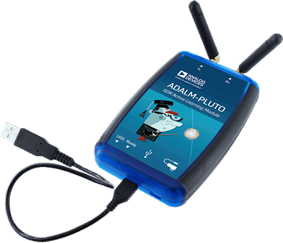
- Analog devices ADALM-PLUTO software-defined radio
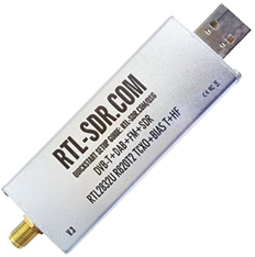
- RTL-SDR
Variables and Ranges
| Name | Value or Range | Default |
|---|---|---|
center_freq |
915 MHz or thereabouts | |
samp_rate |
1 MS/s | |
signal_freq |
-100 kHz to 100 kHz | 20 kHz |
tx_attenuation |
0 to 100 | 10 |
rx_gain |
0 to 70 | 10 |
sps |
100 |
The value of sps won’t be needed in the first half of the lesson, but will arise in the second half when we modulate the carrier signal to send a stream of logical bits (zeros and ones).
Pay attention to the colored background of parameters. If the background is green, the value has to be an integer. This is particularly true of the PlutoSDR. If you run into problems, just surround the expression you have with int().
Directions
-
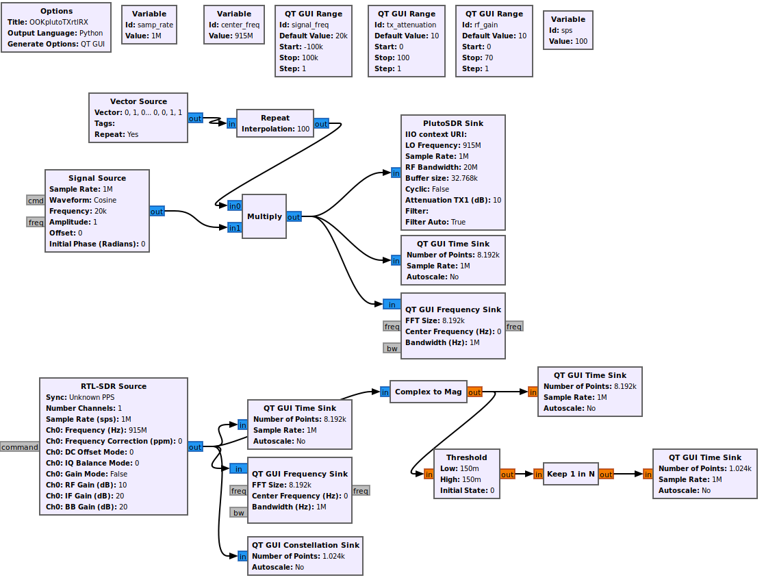
Set up the PlutoSDR to transmit a complex cosine wave at
center_freq, along with the usual QT GUI Time Sink and QT QUI Frequency Sink blocks to show the TX signal. Link up the TX attenuation to the corresponding slider, to enable you to adjust the strength of the transmitted signal. - Add a RTL-SDR Source, which will listen for a signal at
center_freqfor us initially to display, to check for strength and distortion, but which we will eventually want to process to decode the information (bits) broadcast by the PlutoSDR. Add the usual time and frequency sinks to display the output of the RTL-SDR and run the flow diagram.- Does the RTL-SDR report the same signal that the PlutoSDR claims to send?
- If not, how different are the frequencies of the two devices? Hint: if you send in a signal at 0 Hz, what should you expect to receive?
- Is the frequency difference dependent on the temperature of the devices? You might be able to cool one or warm the other to check for a shift in the received frequency.
- Assuming that the devices have attained stable temperatures, can you figure out a way to eliminate their frequency difference?
- Try changing the default number of points in the QT GUI Time Sink by 2, 4, 8, or 16. Does changing the FFT Size change the frequency shift between the two devices?
-
We have now successfully transmitted a carrier wave from the PlutoSDR to the RTL-SDR, albeit with some undesired frequency shifts that arise because the device clocks are independent and unsynchronized. However, a pure sine wave carries no information content. To send something “interesting,” we need to modulate the carrier wave in some fashion. In this lesson, we will use a simple (and inefficient!) approach to this task to send a repeating sequence of ones and zeros by multiplying the carrier wave by 0 to send a 0 bit and 1 to send a 1 bit.
In subsequent lessons, we will learn more sophisticated approaches. For the present, we will specify the binary digits to send in a Vector Source which we will pipe through a Repeat block to send each digit 100 times before switching to the next digit in the code. Use a Multiply block to combine the Signal Source with the repeated vector source to produce the signal that you send to the PlutoSDR Sink (and the corresponding GUI displays). Edit the Vector Source to send a vector with a distinct pattern of zeros and ones. Then, run the flow diagram and compare the signals being sent via the PlutoSDR and the signal received by the RTL-SDR. Do they appear similar? Can you identify the pattern of binary digits that you chose to send?
-
Add a QT GUI Constellation Sink to the output of the RTL-SDR Source to display the signal on the complex plane. Does it look like a “circle”? When the bit is 1, the signal should move around the unit circle on the complex plane, but when it is zero, it should collapse to the origin. Of course, there will be noise in the real signal, so the points would trace out a perfect circle or a pure point at the origin. Nonetheless, can you see the basic pattern? Our next task is to turn this observation into decoded binary bits.
- Use a Complex to Mag block to convert the output of the RTL-SDR source into a real number representing its amplitude. Run the flow diagram and adjust the gains and attenuations to produce a signal that seems to faithfully reproduce the information you are aiming to broadcast. Then install a Threshold block to trigger when the signal makes a transition between the “0” state and the “1” state. You can set both the low and high threshold to the same value. Then, it is helpful to undo the repeat operation that we applied to the output of the vector source to produce the pure digital information that we aimed to transmit. Use a Keep 1 in N block with N set to the same value you used in the Repeat block and send the output to a time sink.
Things to Explore
Note: Depending on your hardware, you may find that displaying all the plots causes errors. You may find that disabling ones that arise earlier in the chain that you are not observing frees up enough computing power to avoid the errors.
Plotting what you are sending and receiving on the same plot: can
Play with the transmission
meaning of sending a constant
OOK from Pluto to RTL-SDR
Making data from various sources: list the data explicitly with a Vector Source sps = samples per symbol (sets 100 samples per symbol)
How to convert from signal back to bits: amplitude of the complex number. Shows with a constellation plot.
threshold: then keep 1 in N where N is sps
Homework
- transmit other bit patterns
- how fast can you go
- how far away can you put the transmitter and receiver?